Welcome to ProDev WorkShop, a major part of the Developer Magic[tm] software development environment. ProDev WorkShop is a software toolset for the development of C, C++, Ada, and Fortran applications. These powerful, highly visual tools help you understand your program's structure and operation so that you can diagnose very difficult, traditionally time-consuming problems in a short amount of time. With them, you can develop applications for the entire Silicon Graphics® product line, from Indy[tm] to POWER Onyx[tm] workstations.
 | Note: In the past, the software development environment was called CASEVision[tm]; that name has been replaced by Developer Magic. In addition to ProDev WorkShop, the Developer Magic environment includes ProMPF—a special module for multi-process Fortran programming—and IDO (IRIX Development Option)—the base compiler and libraries. Some of the documentation may still use the CASEVision name; those documents will be updated soon. |
The ProDev WorkShop toolset provides:
Comprehensive control over the debugging process—You can set simple breakpoints with the click of a mouse button or define complex conditions for your traps. ProDev WorkShop's fast data watch points with kernel support are especially adept at tracking memory corruption problems.
Visual debugging environment for examining data in your active program—ProDev WorkShop provides convenient, graphical views of variables, expressions, large arrays, and data structures. If you prefer a tty-style interface, you can always dump values directly using WorkShop's Debugger command line.
Powerful static analysis for understanding your program—You can view the structure of your program and relationships such as call trees, function lists, class hierarchies, and file dependencies. And you can get this information whether or not the program can be compiled.
The ability to collect performance and coverage information during test runs—ProDev WorkShop's Performance Analyzer lets you see where your program spends its time and pinpoint performance bugs, including those due to memory problems. The Tester tool shows you which source lines and basic blocks are covered in your tests.
Convenient recompiling from within the ProDev WorkShop environment—WorkShop's standard build tools let you view file dependencies and compiler requirements and fix compile errors conveniently.
Quick recompiles for simple changes—The Fix and Continue tool lets you make simple changes without having to go through a major recompile and relinking, dramatically reducing the number of edit-compile-debug cycles.
Ability to analyze structures and relationships in C++ and Ada code—The Browser provides global graphical and textual views of relationships between language-specific entities, including inheritance, containment, and interactions.
Specialized debugging for X/Motif® applications—The X/Motif Analyzer lets you solve the special problems in X/Motif application development. You can look at object data, set breakpoints at the object or X protocol level, trace X and widget events, and tune performance.
Rapid application development—The RapidApp tool lets you create graphical interfaces for C++ applications quickly and easily. RapidApp lets you build graphical interfaces by dragging and dropping interface elements (based on IRIX IM (X/Motif) widgets and IRIS ViewKit[tm]-style components) onto a template window.
This overview gives you a broad exposure to the ProDev WorkShop toolset as well as pointers to the documentation for getting detailed information. The overview is organized as follows:
In addition to the ProDev WorkShop tools, you can separately purchase:
Developer Magic Pro MPF—a visual code parallelization tool used with the Power Fortran Accelerator[tm] to help balance parallel loops in Fortran applications
Developer Magic ClearCase[tm]—a toolset for version control, configuration management, and process control for software organizations
Note: If you use ClearCase, SCCS, or RCS, you can check source files directly into or out of ProDev WorkShop and MegaDev. Developer Magic Tracker—an application builder for creating change control and change tracking systems. It can be integrated with ClearCase.
The Debugger is a UNIX® source-level debugging tool that provides special windows (views) for displaying program data and execution state as the program executes. The Debugger lets you set various types of breakpoints and watch points where you can conveniently view data such as variables, expressions, structures, large arrays, call stacks, and machine-level values. The WorkShop Debugger goes far beyond the capabilities of dbx. It includes fast data watchpoints and other types of traps; graphical views for displaying local variables, source-level expressions, array variables, and data structures; and debugging at the machine level.
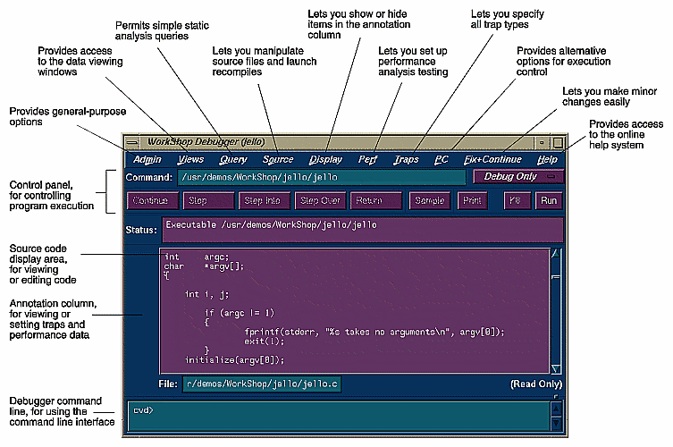
All WorkShop activities can be accessed from the Main View window, which is illustrated in Figure 1.
The basic model for using the Debugger is to:
Invoke the Debugger by typing:
cvd [-pid pid] [-host host] [executable [corefile]] [&]
The -pid option lets you attach the Debugger to a running process. You can use this to determine why a live process is in an infinite loop or is otherwise hung.
The argument executable is the name of the executable file for the process you want to run. It is optional; you can invoke the Debugger first and specify the executable later.
The corefile option lets you invoke the Debugger and specify a core file (with its executable) to try to determine why a program crashed.
The -host option lets you specify a remote host on which the target executable will be run; the Debugger runs locally. This option is useful if:
you don't want the Debugger windows to interfere with the application you are debugging.
you are supporting an application remotely.
you don't want to use the Debugger on the target system for another reason.
Set stop traps, that is, breakpoints, in the source code.
Simple traps are set by clicking the left mouse button in the annotation column to the left of the source code display or by using the Traps menu. More complex traps, including watch points, can be set and managed from the Trap Manager, Signal Panel, and Syscall Panel, which can be accessed from the Views menu. You can also set traps by typing them at the Debugger command line in Main View. You can stop a process at any time by clicking the Stop button in the Main View control area.
Start the program by clicking the Run button in Main View.
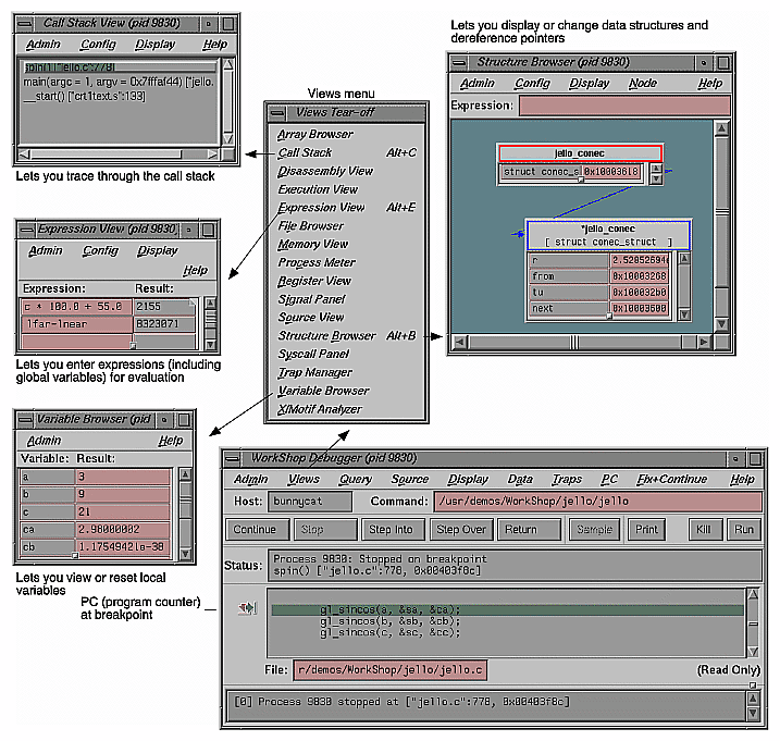
When the process stops at a trap or other stopping point of interest, you can examine the data in the Debugger view windows (accessed from the Views menu).
You can display view windows at any time; they update automatically each time the program stops. Figure 2 shows four typical Debugger views and indicates how you access them from the Views menu.
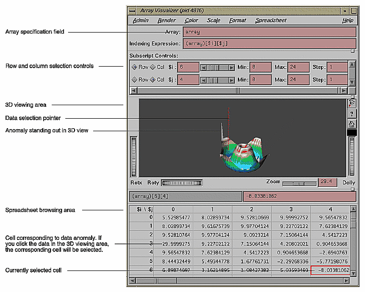
Figure 3 shows the Array Visualizer, a powerful view for examining data in arrays of up to 100 x 100 elements. You can look for problem areas in a 3D rendering of the array, click on the area of interest, and view the numerical values in a spreadsheet format. In Figure 3, the hue option has been set so that the values appear in a color spectrum from blue (lowest) to red (highest) with out-of-range anomalies appearing in gray. Note the high point coming out of the 3D image; it demonstrates how anomalies in large arrays stand out.
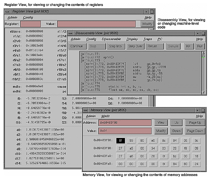
If you need to debug your program at the machine level, you can use Register View, Disassembly View, and Memory View, as shown in Figure 4. These are accessed from the Views menu in the Debugger Main View as well.
Use the control panel options in Main View to continue execution (see Figure 1).
From any breakpoint, you have these options:
The Continue button runs the program until the next breakpoint.
The "Continue To" selection in the PC menu proceeds to a specified source line. Placing the cursor in a line specifies it.
The "Jump To" selection in the PC menu goes to a specified line (by the cursor), skipping over any intermediate code.
The Step Into button continues execution by one step or a number specified by holding down the right mouse button over the Step Into button and selecting the number from the dialog box. The process then continues the specified number of source lines and enters any called functions.
The StepOver button similarly proceeds a specified number of lines but executes intermediate functions without stepping into them.
The Return button executes the remaining instructions in a function and stops on return from that function.
Check out the source code that needs to be fixed.
If you find a bug and are using an integrated source control program such as ClearCase, RCS, or SCCS, you can check out the source code from Main View (or Source View, an alternate editing window).
Choose "Check Out" from the Versioning submenu in the Source menu.
Fix any problems in your code using the source code display area in Main View, Source View, or the editor of your choice.
Both Main View and Source View let you do simple editing and annotate the code with trap indicators. Source View also lets you display test data from the Performance Analyzer and Tester in the annotation column. If you prefer to view source code in a text editor other than Source View, add the line
*editorCommand: editor
to your .Xdefaults file, where editor is the command for the editor you wish to use.
Recompile using Build Manager.
Build Manager has two windows: Build View and Build Analyzer. Build View lets you compile, view compile error lists, and access the offending code in Source View or an editor of your choice. Build Analyzer lets you view build dependencies and recompilation requirements, and access source files. Build View uses the UNIX make facility as its default build software. Although Build Analyzer determines dependencies using make, you can substitute the build software of your choice, any make that runs on Silicon Graphics platforms.
To find out more about the Debugger, refer to Table 1.
Table 1. Where to Find Debugger Information in the Developer Magic: Debugger User's Guide
Topic | See ... |
|---|---|
General Debugger information | Chapter 1, "Getting Started with the WorkShop Debugger" |
Debugger tutorial | Chapter 3, "A Short Debugger Tutorial" |
Debugger interaction with source files | Chapter 2, "Managing Source Files" |
Managing windows while performing multiple tasks | "Project Session Management Windows" |
Comprehensive trap information | Chapter 4, "Setting Traps" |
Controlling execution in a process (stepping, jumping, etc.) | Chapter 5, "Controlling Process Execution" |
Examining Debugger data in general at the source level | Chapter 6, "Examining Debugger Data" |
Tracing through the call stack | "Tracing Through Call Stack View" |
Entering expressions to be evaluated at stopping points | "Evaluating Expressions" |
Viewing or changing the values of variables | "Variable Browser" |
Examining data in arrays using the 3D or spreadsheet format | "Array Browser" |
Determining the data structures of variables | "Structure Browser" |
Using the Debugger command line | "Debugger Command Line" |
Examining debugger data at the machine level | "Machine-level Debugging Windows" |
Using the debugger to trap memory allocation problems | Chapter 8, "Detecting Heap Corruption" |
Debugging multiprocess programs | "Multiple Process Debugging Windows" |
The ProDev WorkShop Static Analyzer is a source code analysis and navigation tool for analyzing source code written in C, C++, Fortran, or Ada (with purchase of ProDev Ada only). (The Browser has additional features for Ada and C++ and is described in "Browser User Model".) The Static Analyzer shows you the code's structure (graphically or in text format) including function calls, definitions of variables, file dependencies, macro locations, class hierarchies, file dependencies, and other structural details for understanding your code. You can also make specific queries, such as showing where a function is used. You can even analyze programs that don't compile, a particularly nice feature for those porting code.
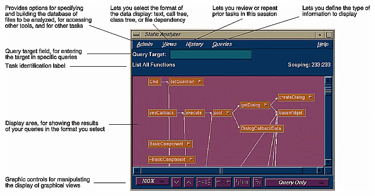
The Static Analyzer works by reading through source code files that you specify and creating a database of program elements such as functions, files, classes, methods, packages, and their relationships. The main Static Analyzer window with a typical call graph is illustrated in Figure 5.
Follow these steps for using the Static Analyzer:
Invoke the Static Analyzer, either by typing cvstatic or by selecting "Static Analyzer" from the Launch submenu in any ProDev WorkShop Admin menu (preferably from the directory where your source is located).
Decide which files are to be analyzed.
You designate which files are to be analyzed in a special file called a fileset. A fileset is a regular ASCII file with a format of one entry per line, each line separated from the next by a carriage return. The entries can be regular expressions, filenames, or included directories preceded by the designator -I.
To specify a fileset, you can
create the fileset manually using a text editor
use the Fileset Editor, which is accessed from the Admin menu in the Static Analyzer window
let the Static Analyzer create the fileset automatically at startup by defaulting to the files in the current directory that match the expression *.[cCfF]
let the Static Analyzer create the fileset automatically at startup from the command line by typing cvstatic with the -executable flag and designating an executable
use the compiler to create a fileset (and database) by adding the -sa,<dbdirectory> option to your makefile
Note: Many programs are so big that a query covering the entire scope is useless due to its size and complexity. There are two ways to keep the scope of your analysis at a manageable size: (1) Limit the number of files to be analyzed or (2) avoid queries that begin with "List All ...". Decide how you are going to build the database.
Before you can specify a fileset, you must decide how you are going to build the database. You can choose to create the database in scanner mode (the default), which is fast but not sensitive to any specific programming language, or in parser mode, which uses the compiler and is slower but more thorough. Use scanner mode for large programs or for programs that do not compile. Scanner mode is particularly suited to porting situations. Parser mode is better when you have code that compiles and you need to determine language-specific relationships, particularly in Fortran, Ada, and C++.
Build the database.
Perform your queries.
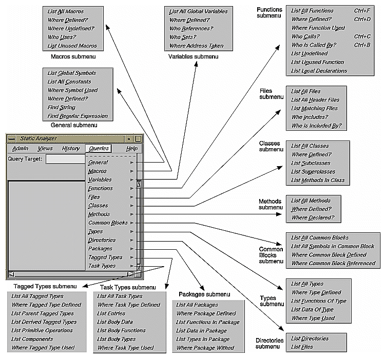
Queries are selected from the Queries menu in the Static Analyzer. They fall into 13 categories, as shown in Figure 6. Remember that the "List All ..." queries can produce overwhelming results for large programs.
View (and save) the results.
The Static Analyzer has four ways of presenting data, which are selected from the Views menu:
"Text View" displays query results in a text format. In addition to listing the queried items, it indicates the source filename and line number, and includes the actual source line.
"Call Tree View" applies to function queries. It presents the data in a graphical format with nodes (rectangles) representing functions and arcs (arrows) representing calls to functions.
"Class Tree View" applies to C++ class queries. It presents a class inheritance tree with nodes representing classes and arcs representing parent-child class relationships.
"File Dependency View" applies to file queries. It presents a graph, with nodes representing files and arcs representing include relationships.
If you want to save a query in a graphical view, you can save a PostScript® version by selecting "Save Query..." from the Admin menu and print it out at your leisure.
Access the source code.
Double-clicking any node in a graph or item in Text View brings up the Source View window containing the corresponding source code. Double-clicking any arc (arrow) displays Source View with the corresponding call site or file inclusion.
To find out more about the Static Analyzer, refer to Table 2.
Table 2. Where to Find Static Analyzer Information in the Developer Magic: Static Analyzer and Browser User's Guide
Topic | See ... |
|---|---|
General Static Analyzer description | Chapter 1, "Introduction to the WorkShop Static Analyzer" |
Static Analyzer tutorial | Chapter 2, "A Sample Session With the Static Analyzer" |
Specifying a fileset | "Fileset Specifications" |
Building a database using scanner mode | "Scanner Mode" |
Building a database using parser mode | "Parser Mode" |
Performing queries | Chapter 4, "Static Analyzer: Queries" |
Static Analyzer viewing formats | Chapter 5, "Static Analyzer: Views" |
Strategies for analyzing large programs | Chapter 6, "Static Analyzer: Working on Large Programming Projects" |
The Browser user model is similar to the Static Analyzer user model. After you build the database (which must be done in parser mode), you access the Browser by selecting "Browser" from the Static Analyzer Admin menu.
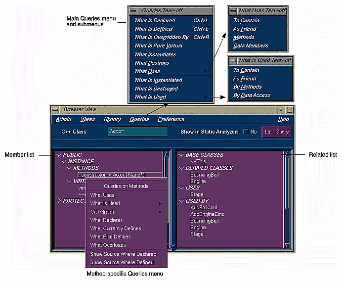
The Browser lets you display different sets of information including relationships about C++ classes and members, Ada packages, tagged types, tasks, and their members through these three views:
Browser View—displays member and related information in an expandable, hierarchical outline format with the members of the current class, package, tagged type, or task in the left pane and related elements on the right (see Figure 7). Clicking the diamond-shaped icons next to the headings in the list hides or displays the associated information.
Like the Static Analyzer, you have numerous queries available through the Query menu. In addition, if you select an item in either of the Browser View lists and hold down the right mouse button, you can access the Queries menu specific to that type of item, that is, methods, data members, classes, and so on.
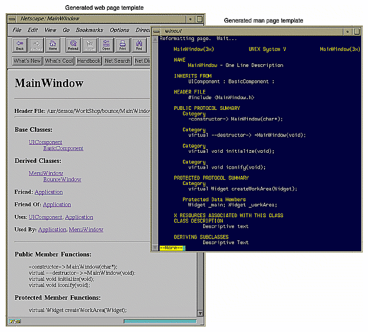
You can create man page templates for classes, packages, tasks, or tagged types by selecting "Generate man pages..." from the Browser View Admin menu. You simply specify one or more elements, click the Generate button, and the Browser fills in the man page template for you. Similarly you can create web pages by selecting "Generate web pages..." from the Browser View Admin menu. See Figure 8.
Class Graph—displays the hierarchy for the current subject in the Browser View window with nodes as subjects and arcs as relationships. Class Graph can show four types of relationships: inheritance, containment, interaction, and friends. You can display all subjects, limit the scope to those derived from the current subject, or get a butterfly view showing the immediate base and derived subjects of the current one.
Call Graph—displays the calling relationships of methods, virtual methods, or functions selected from Browser View with options for customizing the display of the graph.
To find out more about the Browser, refer to Table 3.
Table 3. Where to Find Browser Information in the Developer Magic: Static Analyzer and Browser User's Guide
Topic | See ... |
|---|---|
General Browser description | Chapter 7, "Getting Started with the Browser" |
C++ Browser tutorial | Chapter 8, "Using the Browser for C++: A Sample Session" |
Ada Browser tutorial | Chapter 9, "Using the Browser for Ada: A Sample Session" |
Detailed reference information | Chapter 10, "The Browser Reference" |
Browser View window | "Browser View Window" |
Class Graph window | "Class Graph Window" |
Call Graph window | "Call Graph Window" |
Generating man pages | "Man Page Generation" |
Generating web pages | "Web Page Generation" |
The ProDev WorkShop Performance Analyzer helps you understand how your program performs so that you can correct any problems. In performance analysis, you run experiments to capture performance data and see how long each phase or part of your program takes to run. You can then determine if the performance of the phase is slowed down by the CPU, I/O activity, memory, or a bug and attempt to speed it up.
A menu of predefined tasks is provided to help you set up your experiments. With the Performance Analyzer views, you can conveniently analyze the data. These views show CPU utilization and process resource usage (such as context switches, page faults, and working set size), I/O activity, and memory usage (to capture such problems as memory leaks, bad allocations, and heap corruption).
The Performance Analyzer has three general techniques for collecting performance data:
Counting—It can count the exact number of times each function and/or basic block has been executed. This requires instrumenting the program, that is, inserting code into the executable to collect counts.
Profiling—It can periodically examine and record the program's PC (program counter), call stack, and resource consumption.
Tracing—It can trace events that affect performance, such as reads and writes, system calls, page faults, floating point exceptions, and mallocs, reallocs, and frees.
Set up a general experiment to determine areas for improvement in your program.
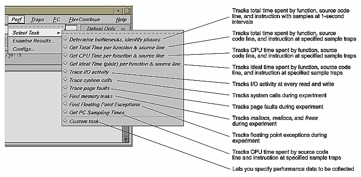
To set up a performance experiment, select a task from the Select Task submenu in the Perf menu in the Debugger Main View. The task menu lets you select predefined experiment tasks (see Figure 9). At this point, you probably haven't formed a hypothesis yet about where the performance problems lie. If this is the case, select the "Determine bottlenecks, identify phases" task. This is useful for determining the general problem areas within the program.
Start the program by clicking the Run button in Main View.
This runs the experiment and collects the performance data, which is written to a directory test0000 (or a name of your choice); test0000 is the identification for your experiment.
Analyze the results in the Performance Analyzer window and the Usage View (Graphs) window.
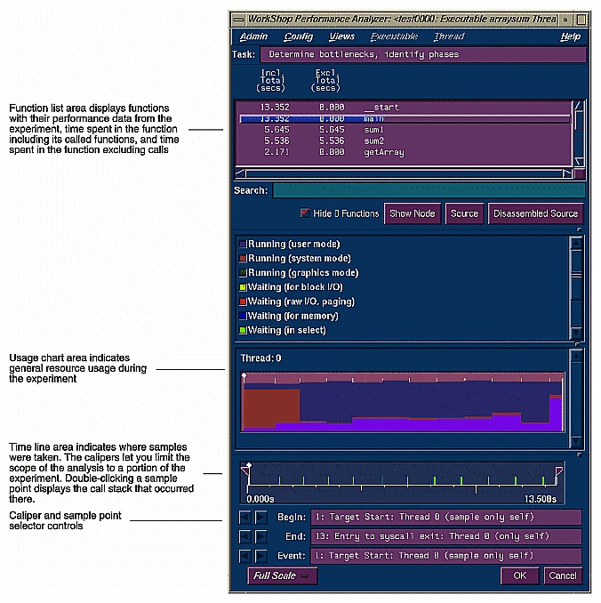
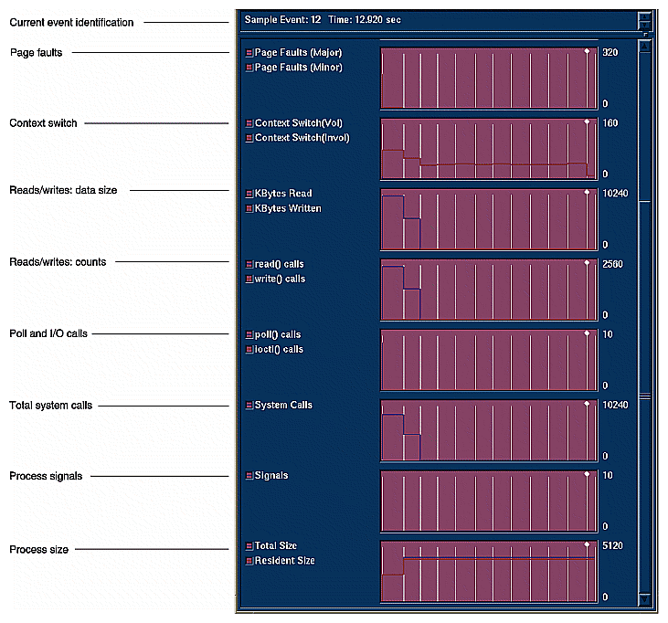
After the experiment has finished, you can display the results in the Performance Analyzer window by selecting "Performance Analyzer" from the Launch submenu in any ProDev WorkShop Admin menu or by typing cvperf -exp experimentname. The results from a typical performance analysis experiment appear in Figure 10, the main Performance Analyzer window, and Figure 11, which shows a subset of the graphs in the Usage Views (Graphs) window. You should be able to determine where the phases of execution occur so that you can set sample traps between them. Sample traps collect performance data at specified times and events in the experiment.
Set sample traps at the start and end of each phase.
Setting sample traps between phases isolates the data to be analyzed on a phase-by-phase basis. Sample traps are set by selecting "Sample", "Sample at Function Entry", or "Sample at Function Exit" from the Set Trap submenu in the Traps menu in the Debugger Main View or through the Traps Manager.
Select your next experiment from the Task Menu in the Performance Panel and run it by clicking the Run button in the Main View window.
You need to form a hypothesis about the performance problem and select an appropriate task (see Figure 9) for your next experiment. There are trade-offs in selecting tasks—experiments can collect huge amounts of data and may perturb the results in some cases.
Analyze the results using the Performance Analyzer main window, its views, or Source View with performance data annotations displayed.
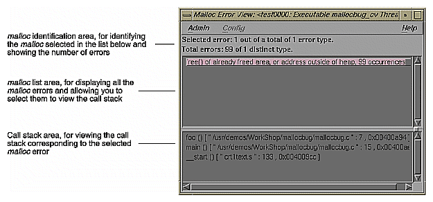
A typical Performance Analyzer view, Malloc Error View, is shown in Figure 12. The Performance Analyzer provides results in the windows listed in Table 4.
Table 4. Performance Analyzer Views and Data
Performance Analyzer Window
Data Provided
Performance Analyzer main window
Function list with performance data, usage chart showing general resource usage over time, and time line for setting scope on data
Call Stack View
Call stack recorded when selected event occurred
Usage View (Graphs)
Specific resource usage over time, shown as graphs
Usage View (Numerical)
Specific resource usage for selected (by caliper) time interval, shown as numerical values
Call Graph View
A graph showing functions that were called during the time interval, annotated by the performance data collected
I/O View
A graph showing I/O activity over time during the time interval
Malloc View
A list of all mallocs, their sizes and number of occurrences, and, if selected, their corresponding call stack within the selected time interval
Malloc Error View
A list of malloc errors, their number of occurrences, and if selected, their corresponding call stack within the time interval
Leak View
A list of specific leaks, their sizes and number of occurrences, and if selected, their corresponding call stack within the time interval
Heap View
A generalized view of heap memory within the time interval
Source View
The ProDev WorkShop text editor window showing source code annotated by performance data collected
Working Set View
The instruction coverage of dynamic shared objects (DSOs) that make up the executable, showing instructions, functions, and pages that were not used within the time interval
Cord Analyzer
The Cord Analyzer is not actually part of the Performance Analyzer, but it works with data from Performance Analyzer experiments. It lets you try out different ordering of functions to see the effect on performance.
To find out more about the Performance Analyzer, refer to Table 5.
Table 5. Where to Find Performance Analyzer Information in the Developer Magic: Performance Analyzer and Tester User's Guide
Topic | See ... |
|---|---|
General Performance Analyzer information | Chapter 1, "Introduction to the Performance Analyzer" |
Performance analysis theory | "Sources of Performance Problems" |
General Performance Analyzer tutorial | Chapter 2, "Performance Analyzer Tutorial" |
Memory leak tutorial | "Memory Experiment Tutorial" |
Setting up performance analysis experiments including task selection | Chapter 3, "Setting Up Performance Analysis Experiments" for details and "Selecting Performance Tasks" for a summary |
Setting sample traps | Chapter 4, "Setting Traps" in the ProDev WorkShop Debugger User's Guide |
Performance Analyzer main window | "The Performance Analyzer Main Window" |
Usage View (Graphs) window | "Usage View (Graphs)" |
Watching an experiment without collecting data in the Process Meter | "Process Meter" |
Usage View (Numerical) window | "Usage View (Numerical)" |
Tracing I/O calls using the I/O View window | "I/O View" |
Call Graph View window | "Call Graph View" |
Finding memory problems | "Analyzing Memory Problems" |
Specifying performance annotations for Source View and Call Graph View | "Config Menu" |
Call Stack View window | "Call Stack" |
Improving working set behavior | "Analyzing Working Sets" |
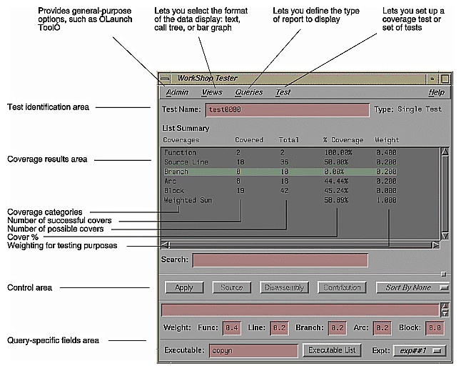
Tester is a software quality assurance toolset for measuring dynamic coverage over a set of tests. It tracks the execution of functions, individual source lines, arcs, blocks, and branches.
This section describes the user model for designing a single test. After you have your instrumentation file and test directories set up, you can automate your testing and create larger test sets. Tester has both a command line interface (see Table 6) and a graphical user interface (see Figure 13).
Plan your test.
Create (or reuse) an instrumentation file.
The instrumentation file defines the coverage data you wish to collect in this test.
Apply the instrument file to the target executable(s).
This creates a special executable for testing purposes that collects data as it runs.
Create a test directory to collect the data files.
Run the instrumented version of the executable to collect the coverage data.
Analyze the results.
Tester produces a wide variety of column-based reports. Most are available in both interfaces: command line and graphical. The reports can show source and assembly line coverage; coverage of functions; arc coverage, that is, coverage of function calls; call graphs indicating caller and callee functions and their counts; basic block counts; count information for assembly language branches; summaries of overall coverage; and argument tracing.
Table 6. Tester Command Line Interface Summary
Command Category
Command Name
Description
general
cvcov cattest
Describes the test details for a test, test set, or test group
cvcov lsinstr
Displays the instrumentation information for a particular test
cvcov lstest
Lists the test directories in the current working directory
cvcov mktest
Creates a test directory
cvcov rmtest
Removes tests and test sets
cvcov runinstr
Adds code to the target executable to enable you to capture coverage data, according to the criteria you specify
cvcov runtest
Runs a test or a set of tests
coverage analysis
cvcov lssum
Shows the overall coverage based on the user-defined weighted average over function, line, block, branch, and arc coverage
cvcov lsfun
Lists coverage information for the specified functions in the program that was tested
cvcov lsblock
Displays a list of blocks for one or more functions and the count information associated with each block
cvcov lsbranch
Lists coverage information for branches in the program, including the line number at which the branch occurs
cvcov lsarc
Shows arc coverage, that is, the number of arcs taken out of the total possible arcs
cvcov lscall
Lists the call graph for the executable with counts for each function
cvcov lsline
Lists the coverage for native source lines
cvcov lssource
Displays the source annotated with line counts
cvcov lstrace
Shows the argument tracing information
cvcov diff
Shows the difference in coverage for different versions of the same program
test set
cvcov mktset
Makes a test set
cvcov addtest
Adds a test or test set to a test set or test group
cvcov deltest
Removes a test or test set from a test set or test group
cvcov optimize
Selects the minimum set of tests that give the same coverage or meet the given coverage criteria as the given set
test group
cvcov mktgroup
Creates a test group that can contain other tests or test groups; targets are either the target libraries or DSOs
To find out more information about Tester, refer to Table 7.
Table 7. Where to Find Tester Information in the Developer Magic: Performance Analyzer and Tester User's Guide
Topic | See ... |
|---|---|
General Tester information | "Tester Overview" |
Automated testing | "Automated Testing" |
Command line interface tutorial | Chapter 23, "Tester Command Line Interface Tutorial" |
Graphical user interface tutorial | Chapter 25, "Tester Graphical User Interface Tutorial" |
Command line interface details | Chapter 24, "Tester Command Line Reference" |
Graphical user interface details | Chapter 26, "Tester Graphical User Interface Reference" |
The Build Manager lets you view file dependencies and compiler requirements, fix compile errors conveniently, and compile software without leaving the WorkShop environment. It provides two views:
Build View—for compiling, viewing compile error lists, and accessing the code containing the errors in Source View (the ProDev WorkShop editor) or an editor of your choice.
Build Analyzer—for viewing build dependencies and recompilation requirements and accessing source files.
For more information on Build Manager, see Appendix B, "Using the Build Manager," in the Developer Magic:Debugger User's Guide.
Fix and Continue is part of the Developer Magic MegaDev module. The Fix and Continue feature lets you make minor changes to your code from within WorkShop without having to recompile and link the entire system. You issue Fix and Continue commands in the Debugger Main View window, either by selecting them from the Fix+Continue menu or typing them in directly in the Debugger command line area.
With Fix and Continue, you can edit a function, parse the new function, and continue execution of the program being debugged. Fix and Continue enables you to speed up your development cycle significantly. For example, a program that takes 5 minutes to rebuild through a conventional compile might take 45 seconds using Fix and Continue.
Fix and Continue lets you:
Redefine existing function definitions
Disable, reenable, save, and delete redefinitions
Set breakpoints in and single-step within redefined code
View the status of changes
Examine differences between original and redefined functions
Figure 14 shows you the WorkShop Main View during a Fix and Continue session and explains how to use the Fix and Continue menu.
Invoke the Debugger as you normally would by typing:
cvd [-pid pid] [-host host] [executable [corefile]] [&]
Navigate to the function to be changed.
You can get to the function numerous ways, by selecting "Search..." from the Source menu, typing func functionname at the Debugger command line, or simply scrolling to the location. If you did not use func functionname, you need to place the cursor inside the function.
Select "Edit" from the Fix+Continue menu.
This turns on edit mode, highlighting the function source code. If line numbers are displayed, those in the selected function appear with a two-part number separated by a decimal point. The left part represents the starting line number of the function in the source file before selecting "Edit". The right part renumbers the source within the function to make it easier to keep track of added new lines.
Make your changes to the source code.
You can do this directly in Main View or you can use a preferred editor by selecting "External Edit" from the Fix+Continue menu.
Try out your changes.
Selecting "Parse And Load" adds your changes to the executable you are debugging. The changed function will get executed the next time it is invoked. If you stopped in the edited function, the Debugger will let you continue from the corresponding line in the new function, barring certain restrictions.
If the changes are satisfactory, save them for later compiling.
"Save File+Fixes As..." saves the fixes in your current file. "Update All Files..." saves all fixes in your current session.
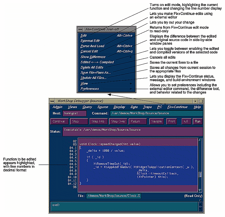
At any point, you can make comparisons with your old code. "Show Difference" displays the old and new source code in a side-by-side format. "Edited<-->Compiled" lets you toggle between the old and new executables making it easy to verify or demonstrate your bug fix.
To find out more information about Fix and Continue, refer to Table 8.
Table 8. Where to Find Fix and Continue Information in the Developer Magic: Debugger User's Guide
Topic | See ... |
|---|---|
General information and tutorial | Chapter 7, "Debugging with Fix+Continue: A Tutorial" |
Detailed command information | "Fix+Continue Windows" |
The X/Motif Analyzer provides special debugging support for X/Motif applications and is available from the WorkShop Views menu. The X/Motif Analyzer operates in a number of modes (referred to as examiners) for examining different types of X/Motif objects. The X/Motif Analyzer provides information unavailable through conventional debuggers. It also lets you set widget-level breakpoints and collect X event history.
When you first invoke the X/Motif Analyzer, it comes up in its Widget Examiner mode. You can switch to the other examiners through the Examiner menu or by clicking the tabs at the bottom of the window (See Figure 15).
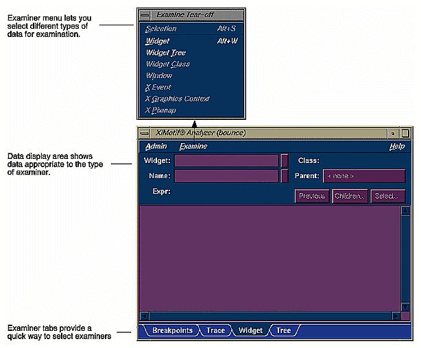
The X/Motif Analyzer provides the following types of examiners:
Widget examiner—identifies a widget's ID, name, class, and parent, and displays its definitions.
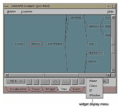
Widget tree examiner—displays the widget hierarchy (see Figure 16). The widgets can be displayed by name, class, or ID by selecting from the widget display menu. Double-clicking a widget node switches to the widget examiner and displays the data for the selected widget.
Breakpoints examiner—lets you set breakpoints at the widget and widget class level. You can set breakpoints at
callback functions
widget events
resource changes caused
timeout callback functions
input callback functions
widget state changes
X events
X requests
Trace examiner—lets you trace the execution of your application and collect the following types of data:
X Server Events
X Server Requests
widget event dispatch information
widget resource changes
widget state changes
Xt callbacks
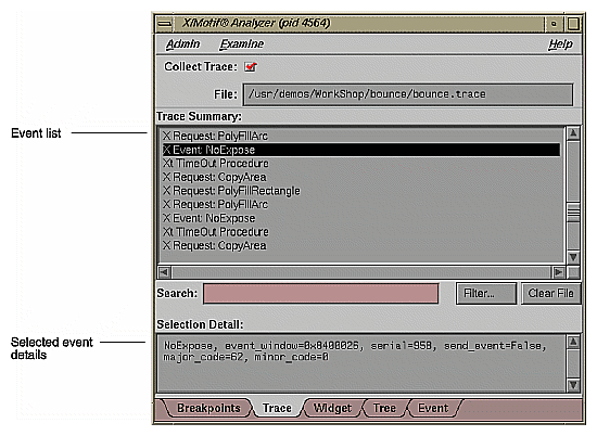
Figure 17 is a typical example of the trace examiner. The events appear in a list. Double-clicking an event displays its details.
Callback examiner—comes up automatically when the process stops in a callback. It displays
the callstack frame for the callback function
widget information
the callback data structure
Window examiner—identifies the window, its parent and any children, and displays window attribute information
Event examiner—displays the event structure for a given XEvent pointer
Graphics context (GC) examiner—displays the X graphics context attributes for a given GC pointer
Pixmap examiner—displays the basic attributes of an X pixmap, including size and depth, and can provide an ASCII display of small pixmaps, using the units digit of the pixel values
widget class examiner—displays the widget class attributes for a given widget class pointer
To find out more information about the X/Motif Analyzer, refer to Table 9.
Table 9. Where to Find X/Motif Analyzer information in the Developer Magic: Debugger User's Guide
Topic | See ... |
|---|---|
General information and tutorial | Chapter 10, "Using the X/Motif Analyzer: A Tutorial" |
Detailed reference information | "X/Motif Analyzer Windows" |
Setting breakpoints to capture widget-level information | "Breakpoints Examiner" |
Tracing widget-level data through the execution of a program | "Trace Examiner" |
Getting information on a specified widget | "Widget Examiner" |
Displaying a graph of the widget hierarchy | "Tree Examiner" |
Getting information on a specified callback | "Callback Examiner" |
Getting information on a specified window | "Window Examiner" |
Getting information on a specified X event | "Event Examiner" |
Getting information on a specified graphics context | "Graphics Context Examiner" |
Getting information on a specified pixmap | "Pixmap Examiner" |
RapidApp is a simple, interactive tool for creating application interfaces. It's integrated with the other WorkShop tools to provide a complete environment for developing object-oriented applications quickly and easily. RapidApp generates C++ code, with interface classes based on the IRIS ViewKit toolkit and IRIS IM (the Silicon Graphics version of X/Motif). RapidApp also includes predefined interface components that allow you to conveniently use other Developer Magic libraries such as OpenGL[tm] and Open Inventor[tm]. Applications produced by RapidApp are automatically integrated into the Indigo Magic Desktop environment, letting you take advantage of Silicon Graphics' interface and desktop technology.
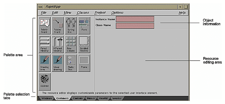
Working with RapidApp is similar to using a drawing tool such as Showcase[tm]. A typical RapidApp window is shown in Figure 18. RapidApp lets you create interface elements by clicking icons representing widgets or components in the palette area, positioning them in a template window, and setting their resources in the editing area.
RapidApp users should be familiar with IRIX IM, IRIS ViewKit, and C++ programming. Here's the basic user model:
Invoke RapidApp by typing rapidapp in the directory in which you wish to build your application.
The RapidApp window is displayed as shown in Figure 18. There are six palettes of icon widgets available. The number of palettes and icons available will increase over time as new, useful widgets are developed. The palettes and icons are:
Container palette—provides container widgets, that is, widgets that can hold other widgets
Controls palette—provides miscellaneous widgets, typically for controls, fields, and so on.
Windows palette—provides simple or special-purpose windows and window-oriented controls, such as menu bars and pulldown menus
ViewKit palette—provides ViewKit components, that is, prepackaged assemblies of widgets from the ViewKit libraries
Inventor palette—provides viewers, editors, and drawing areas compatible with IRIS Inventor[tm]
The process is then one of selecting containers, populating them with widgets, and assembling them into elements of your user interface.
Select a container widget.
A rubber-band box appears, representing the initial default size of the widget. Use the mouse to drag it to a working area on your desktop (or inside another container). After you've positioned the new container widget, you can adjust its size by dragging the corners.
Edit the widget's resources.
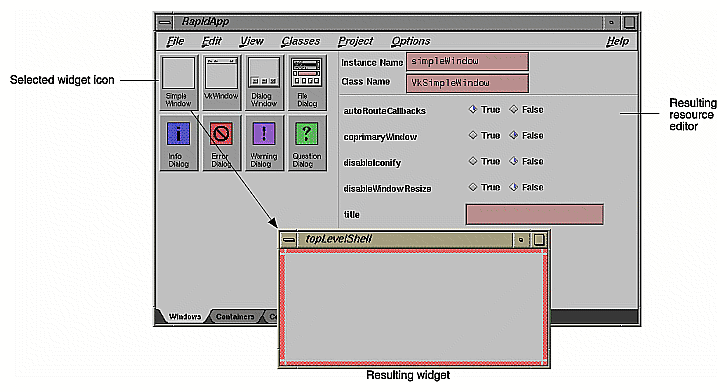
Customize the widget for your application. RapidApp changes the resource editing area according to the type of widget you are working with. It displays text fields for string resources, radio buttons for Booleans, and menus for resources with multiple values. Figure 19 illustrates the creation of a drawing area container widget. The drawing area icon has been selected from the container palette, the new widget has been placed, and the resource editing area has changed accordingly.
Select "Play Mode" from the View menu.
This lets you try out the interface design. When you are through trying it out, go back to working on the interface by selecting "Build Mode" from the View menu.
Perform any further edits on the widget.
Repeat steps 2-5 until your window (or application) is complete.
Select "Generate C++" from the Project menu.
This produces the source code (including Makefile) necessary to implement the interface you have designed. It also displays the Builder information window, a shell that displays RapidApp status messages.
Select "Edit File ..." from the Project menu to make any necessary adjustments to the source code.
A file selection dialog box displays showing the contents of the directory containing the generated source files. When you choose a file, it will appear in your default editor.
Select "Build Application" from the Project menu to compile the new program.
The WorkShop Build View displays and starts a compile going and lets you view any compile errors (see "Recompiling Within the ProDev WorkShop Environment With Build Manager").
Use the other ProDev WorkShop and MegaDev tools, if necessary, to fix any coding problems.
RapidApp is fully integrated with the rest of the Developer Magic environment so that the full range of tools and libraries are at your disposal for completing your application.
To find out more information about RapidApp, refer to Table 10.
Table 10. Where to Find RapidApp Information in the Developer Magic: Application Builder User's Guide
Topic | See ... |
|---|---|
Understanding the RapidApp window | "The RapidApp Interface" in Chapter 1 |
Using RapidApp | "Basic Interaction Techniques" in Chapter 1 and Chapter 3, "Building Interfaces With RapidApp" |
General tutorial | "Example: A Calculator" in Chapter 1 |
Inventor tutorial | Chapter 4, "Example Programs" |
Windows | "Choosing and Using Windows" in Chapter 3 |
Containers | "Using Containers" in Chapter 3 |
Generating software code | Chapter 2, "Creating Applications With RapidApp" |
Applying the other ProDev tools to RapidApp applications | "Debugging and Interactively Adding Functionality" in Chapter 2 |
Detailed reference information | Appendix B, "RapidApp Reference" |